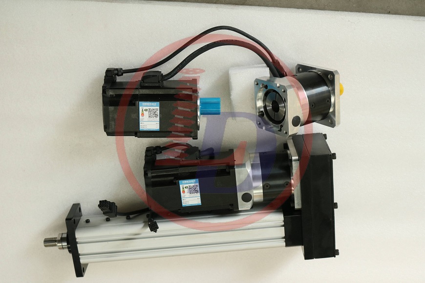
How to check the stability of the lifting spindle of the screw jack and the linear actuator


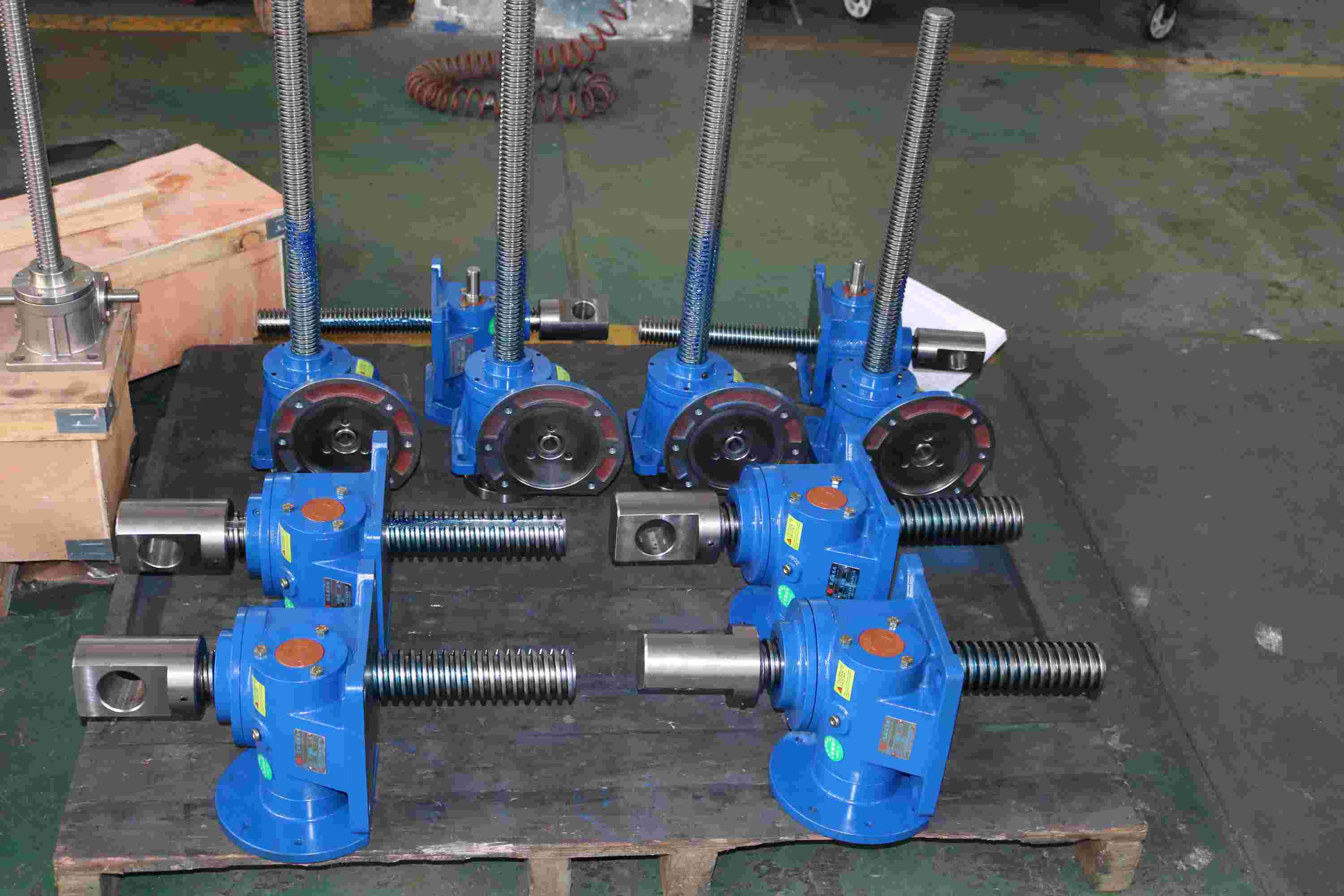
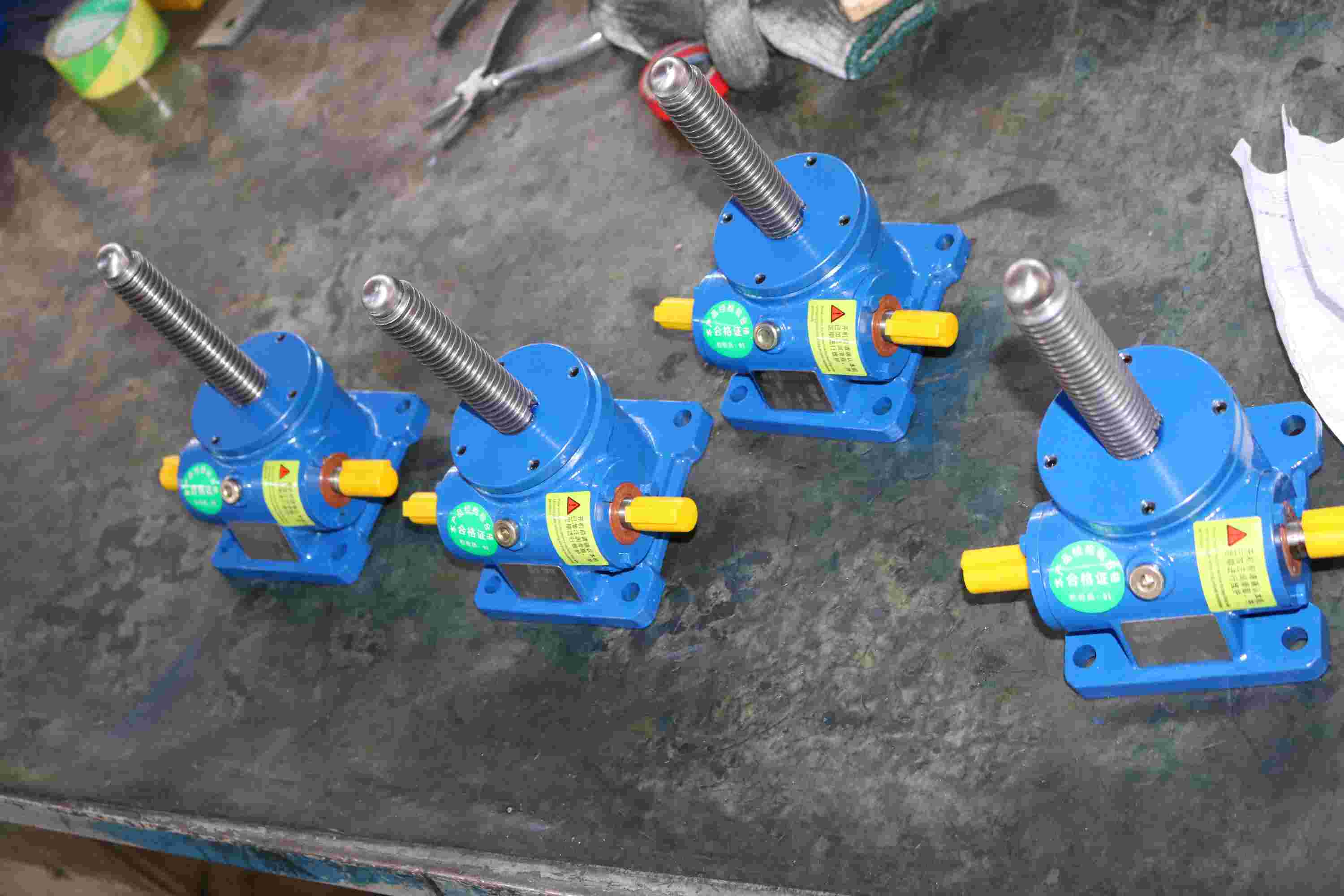
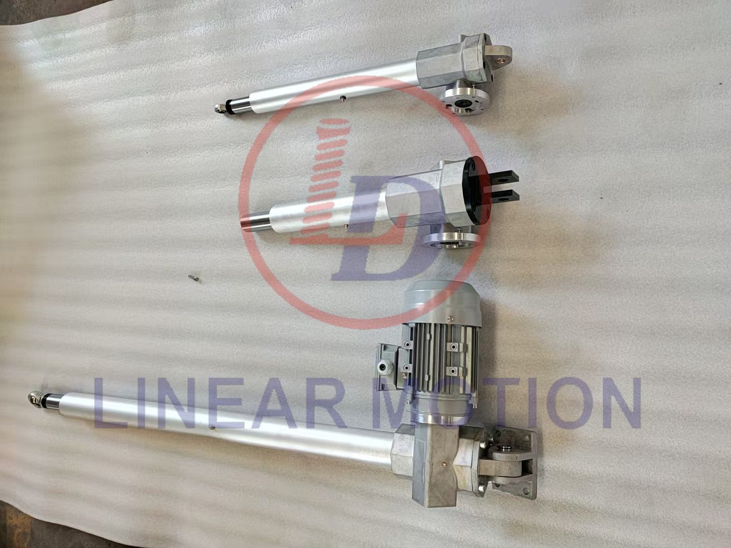
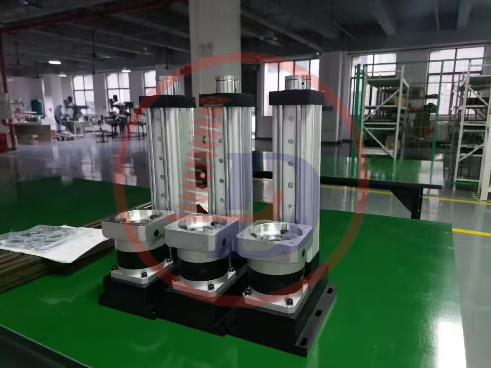
Screw stability verification: known load 100KN, stroke 500mm, speed 60mm/min, no guide rail, usage coefficient 1.5, low operating frequency, calculated model For (Heavy Duty Electric Linear Actuator model SCA200-V1-500-FL-P2):

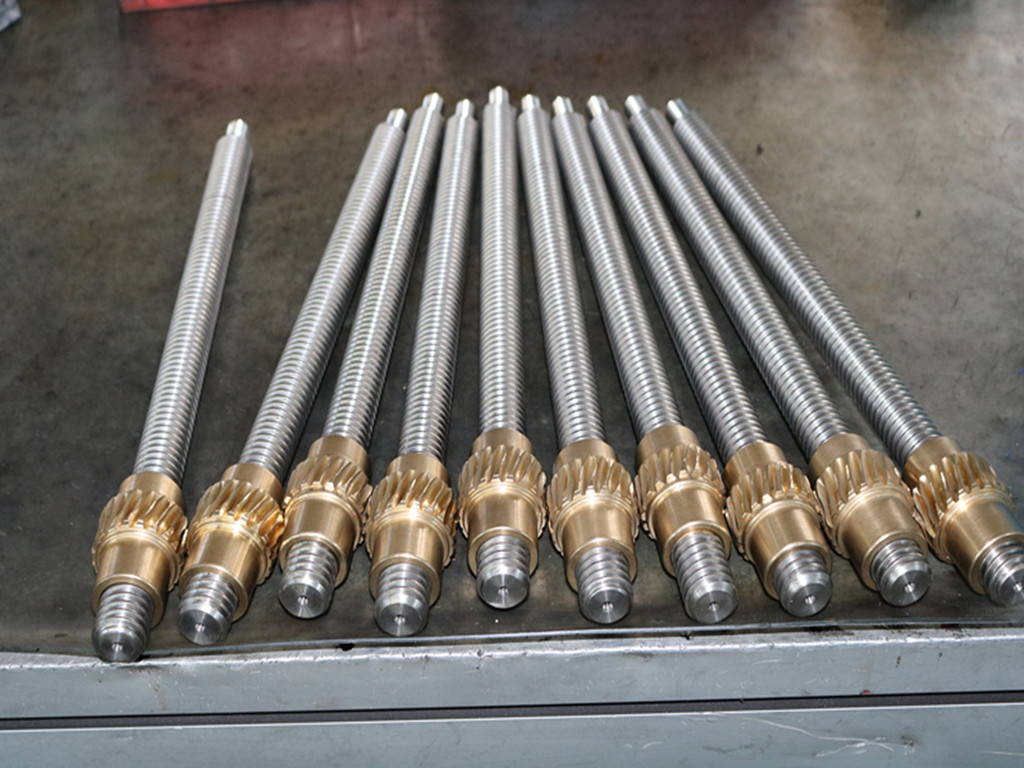
lifting Screw specification Tr80*12

1. Known conditions

Load F=100KN=100,000N

Stroke S=500mm

Speed v=60mm/min

Usage coefficient K=1.5

Screw specification Tr80*12 (diameter 80mm, pitch 12mm)

2. Analysis of screw force

The screw mainly bears the axial load, so we need to calculate the stress of the screw under the axial load.

• Screw diameter d=80mm=0.08m

•Screw cross-sectional area A=π (2d)2= π(20.08)2=0.005027㎡

•Axial load Fax=K*F=1.5×100,00N=150,000N

3. Calculation of screw stress

Screw stress o =AFax=0.00502715000=2983866.67Pa

4. Check the stability of the screw

For the stability of the screw, we mainly pay attention to whether it will flex. Since the screw is usually installed on the fixed bracket and its length is relatively short (500mm), the possibility of buckling is relatively small. However, in order to evaluate more accurately, we can use Euler's formula to estimate the critical bending load of the screw.

1. Screw length=500mm=0.5m

2. The elastic modulus of the screw material E (set to steel, E≈210GPa=210×109Pa)

3. Screw moment of inertia I=π 64d4= π64×(0.08)4=2.01062×10⁻⁷m4

Eular critical load Fcr can be calculated by the following formula:

Fcr=12 π2EI=(0.5)2π 2×210×109×2.01062×10-7=2,649,444.44N

Because Fax=150,000N<Fcr=2,649, 444.44N, the screw is stable under axial load.

5. Summary
After calculation, it is confirmed that the screw (specification is Tr80*12) equipped with the linear actuator model SCA200-V1-500-FL-P2 is at a load of 100KN, stroke of 500mm, speed of 60mm/min, and a coefficient of use of 1.5 And the linear actuator is stable under the condition of low working frequency.

introduction of screw jack's ratio

The transmission ratio of a worm gear screw lift (often just called a worm gear) refers to the ratio between the number of turns the worm (the driving gear) makes for one complete revolution of the worm wheel (the driven gear). This ratio dictates how much mechanical advantage is gained through the system, and also influences the speed reduction and torque increase.

Factors Related to the Transmission Ratio:

  1. Lead of the Worm:

    • The lead is the distance the nut (or worm wheel) moves along its axis per one complete revolution of the worm. It plays a direct role in the transmission ratio.
    • A higher lead results in a faster movement of the worm wheel, but with a higher mechanical advantage (lower ratio) as the gear ratio is influenced by how far the worm travels per turn.
  2. Number of Teeth on the Worm Wheel:

    • The number of teeth on the worm wheel relative to the number of threads on the worm also affects the ratio.
    • In general, the more teeth on the worm wheel relative to the worm, the lower the transmission ratio.
  3. Number of Threads on the Worm:

    • Worms can have one or more threads (called single-start or multi-start worms).
    • A multi-start worm will reduce the transmission ratio, as each turn of the worm moves the worm wheel by a larger distance.
  4. Pitch of the Worm:

    • The pitch (distance between adjacent threads) also influences the ratio. A finer pitch (smaller thread spacing) typically results in a higher transmission ratio.
  5. Friction and Efficiency:

    • Worm gears have a high frictional contact between the worm and the worm wheel, which can influence the effective transmission ratio, especially at higher loads.
    • Efficiency is typically lower in worm gears compared to other types of gears, which can cause some discrepancy between the theoretical and actual ratio.

How to Calculate the Transmission Ratio:

The transmission ratio can be calculated using the following formula:

Transmission Ratio=Number of Teeth on the Worm WheelNumber of Threads on the Worm=ZwZs\text{Transmission Ratio} = \frac{\text{Number of Teeth on the Worm Wheel}}{\text{Number of Threads on the Worm}} = \frac{Z_w}{Z_s}

Where:

  • ZwZ_w = Number of teeth on the worm wheel.
  • ZsZ_s = Number of starts (threads) on the worm.

Example:

If the worm wheel has 40 teeth and the worm has a 2-start thread, the transmission ratio would be:

Transmission Ratio=402=20\text{Transmission Ratio} = \frac{40}{2} = 20

This means for each full rotation of the worm, the worm wheel will turn 1/20th of a rotation.

Additional Considerations:

  • Self-locking feature: Worm gears often have a self-locking property, where the worm can drive the worm wheel but the worm wheel cannot drive the worm. This property comes into play in applications like screw lifts where load holding is important.

Reasons for using electric actuators in photovoltaic power generation

electric linear actuators


Regardless of whether it is a standard electric linear actuator, a small-sized actuator, or even a micro actuator, these devices have seen strong development and application across various industries. One common aspect of their use is their significant role in the renewable energy sector. Here, we will focus on the development of electric actuators in the field of photovoltaic (PV) power generation.

1. Reasons for Applying Electric Actuators in the Photovoltaic Industry
The idea of using electric linear actuators in PV systems emerged due to the high cost of solar panels, which greatly limited the widespread adoption of such products. Under these circumstances, there was a strong need for alternative products, leading to further development of electric electric linear actuators.

2. Development of Electric Actuators in the PV Industry
From the early stages of technology to the present day, photovoltaic power generation has evolved from expensive solar cells to more cost-effective polycrystalline silicon cells, with a significant expansion in application fields. During this process, the use of components has also changed. In the past, fixed brackets were mostly used in power generation systems. However, the current trend has shifted toward actuator-based tracking systems.

3. Recognition of Electric Actuators in the PV Industry
Due to the high efficiency and stability of actuator-based tracking systems, they have received widespread recognition from both the government and industry peers. This has further encouraged investment in this area, ushering in a promising period of development for electric linear actuator tracking systems.

4. Categories of Electric Actuator-Based PV Tracking Systems
This power generation model can be broadly classified into two main types: single-axis linked tracking systems and dual-axis tracking systems. Regardless of the type, electric linear actuators serve as the driving force for these tracking systems. Because of this, strict requirements are placed on their service life—they must match the lifespan of the solar panels in order to maximize the overall efficiency of the PV power generation system.

Electric Actuator-Based PV Tracking Systems

What does the different gear ratio of a worm gear screw jack mean?


The gear ratio (also called the transmission ratio) of a worm gear screw jack refers to the ratio between the rotational speed of the worm and the rotational speed of the screw, usually expressed as the ratio of the worm's speed to the screw's speed. The gear ratio directly affects the speed and output torque of the screw jack.

Meaning of Gear Ratio:

Definition of Gear Ratio:
The gear ratio (Transmission Ratio) is the transmission ratio between the worm wheel and the worm, usually represented by the ratio of the number of teeth on the worm wheel to the number of threads on the worm. For example, if the worm wheel has 50 teeth and the worm has 10 threads, the gear ratio would be 5:1.

Impact on Speed:
The gear ratio determines the relationship between the rotational speed of the worm and the screw. The larger the gear ratio, the slower the worm's speed and the slower the screw's lifting speed. Therefore, a higher gear ratio will slow down the screw's movement, which is suitable for applications requiring precise control. A lower gear ratio will result in faster screw movement, which is suitable for quick lifting needs.

Impact on Torque:
The larger the gear ratio, the greater the torque transmitted from the worm to the screw. In cases of heavy loads, a larger gear ratio can provide higher output torque, allowing the jack to support heavier loads.

  • Low Gear Ratio (e.g., 1:1 or 3:1) typically provides higher speed but lower output torque, making it suitable for light load, high-speed applications.

  • High Gear Ratio (e.g., 10:1 or 20:1) provides greater torque, making it suitable for applications requiring higher load capacity and precision, but with slower speed.

Gear Ratio and Application Scenarios:

Higher Gear Ratio (e.g., 20:1, 30:1):

  • Suitable for high-load, low-speed applications. Due to lower speed, it provides greater torque, making it ideal for heavy-duty equipment or precision-controlled applications, such as precision lifting platforms and large machinery.

  • Typical Applications: Lifting platforms, heavy-duty cranes, precision machinery.

Lower Gear Ratio (e.g., 3:1, 5:1):

  • Suitable for light-load, high-speed applications. Due to the smaller gear ratio, the speed is higher, but the torque is lower, making it suitable for applications that require faster movement but are not designed for heavy loads.

  • Typical Applications: Light-duty conveyor systems, automated production lines, etc.

Impact of Gear Ratio on Self-locking Performance:

Worm gear screw jacks often feature a self-locking function, meaning that when the worm stops turning, the friction generated by the engagement between the worm and the worm wheel prevents the load from automatically sliding down. When the gear ratio is larger, the self-locking ability is stronger, because the engagement angle between the worm and the worm wheel is greater, making it more difficult for the load to move in the opposite direction.


What's the difference between Worm Gear Screw Jack and Bevel Gear Screw Jack?

1. Gear Mechanism

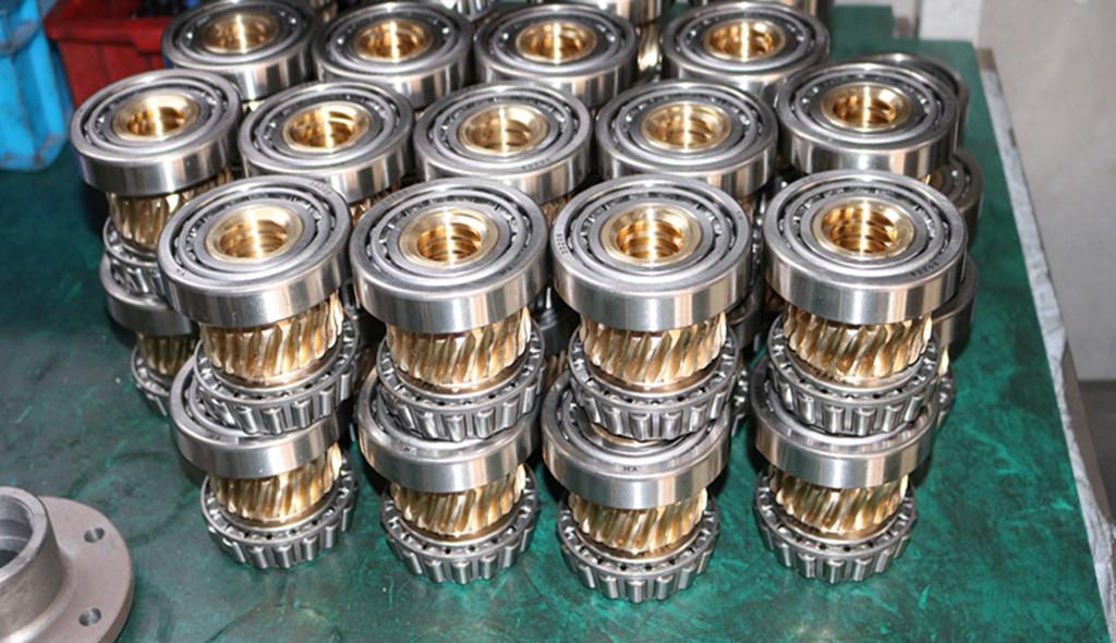
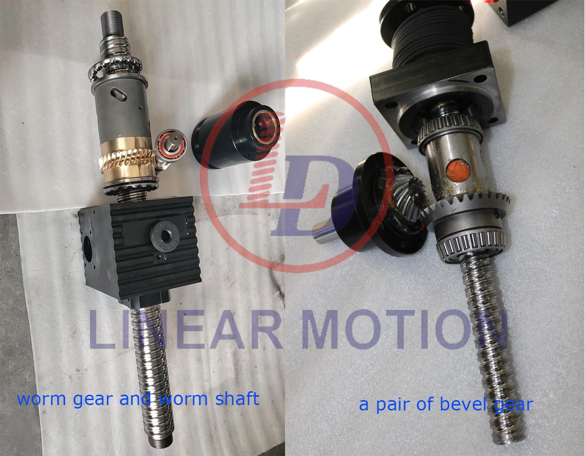
  • Worm Gear Screw Jack: Uses a worm gear mechanism, where a worm (screw) engages with a worm wheel (gear) to transmit motion. The worm gear reduces speed while increasing torque.

  • Bevel Gear Screw Jack: Uses bevel gears, which are conical gears designed to transmit motion between intersecting shafts, typically at a 90-degree angle.

2. Speed and Efficiency

  • Worm Gear Screw Jack: Generally slower but provides higher torque and self-locking capability.

  • Bevel Gear Screw Jack: Offers higher efficiency and faster speed but may require a brake system to prevent back-driving.

3. Load Handling Capacity

  • Worm Gear Screw Jack: Suitable for heavier loads due to its high torque output.

  • Bevel Gear Screw Jack: More suited for applications where high-speed movement and moderate load handling are required.

4. Self-Locking Feature

  • Worm Gear Screw Jack: Typically self-locking, meaning it can hold a load in position without additional braking.

  • Bevel Gear Screw Jack: Not usually self-locking, so an external brake or locking mechanism may be needed.

5. Efficiency & Power Consumption

  • Worm Gear Screw Jack: Less efficient due to friction in the worm gear system, leading to higher power consumption.

  • Bevel Gear Screw Jack: More efficient with lower power consumption due to better mechanical advantage.

6. Application Suitability

  • Worm Gear Screw Jack: Used in applications requiring high force, stability, and safety, such as lifting platforms, heavy machinery, and presses.

  • Bevel Gear Screw Jack: Ideal for applications needing high-speed movement with moderate force, such as automation systems, conveyor adjustments, and stage lifting.


You can choose the appropriate lift according to your working conditions.You can choose the appropriate lifter according to your working conditions. If it is slow, low frequency and self-locking, the worm gear screw lifter is suitable. If it is fast and high frequency, then the bevel gear lifter is suitable.


Why can't the load of servo electric cylinder be too large?

servo electric cylinders

The load capacity of servo electric cylinders cannot be very high mainly due to the following reasons:


1. Servo motor power limitations: Servo electric cylinders are driven by servo motors, which have limited power. When the load is too large, the motor may not be able to provide sufficient torque to move the load, potentially resulting in motor overload or even burnout.

2. Transmission system limitations: Servo electric cylinders typically use mechanical transmission components (such as gears or ball screws) to transfer motion from the motor to the load. Excessive load can put too much stress on these components, leading to wear, damage, or failure.

3. Control system responsiveness: Servo control systems regulate motor operation by adjusting current and voltage. When the load is too heavy, the system may not be able to control the motor precisely, leading to positioning errors, system shutdowns, or overload protection activation.


4. Efficiency issues: High loads can reduce the operational efficiency of the electric cylinder, causing increased heat generation. Excessive load may also affect the effectiveness of the cooling system, raising the system temperature and shortening the lifespan of the electric cylinder.


5. Decreased precision and stability: Servo electric cylinders are typically designed to deliver high-precision motion within a specified load range. Overloading can reduce accuracy and compromise system stability, possibly causing vibrations or abnormal noises.

Therefore, when selecting a servo electric cylinder, it is essential to choose a model that matches the specific application requirements. Ensuring the load remains within the design limits of the cylinder is critical to avoid overload and ensure reliable operation.

servo electric cylinders


Roof Snow Melting Heating Cable Principle, Installation and Suggestions

1. Snow melting principle of heating cable

Electro thermal conversion

The alloy resistance wire inside the cable generates heat after being energized (the surface temperature is generally 40-50℃), and melts the snow through heat conduction, thereby preventing the formation of ice dams.


Self-regulating technology (some high-end models)

Due to the use of PTC materials, the lower the temperature, the lower the resistance, and the greater the heat output, thus achieving automatic power regulation, saving energy, and achieving optimal safety.


Zone control

The system uses temperature and humidity sensors or intelligent controllers and only starts in snowy weather or low temperatures to reduce energy consumption.


2. Installation steps and precautions

  •  Preparation before installation

Land use planning

Cover eaves, gutters and other areas prone to snow and ice accumulation. It is recommended to use "inverted W" or "snake" wiring.


Cable selection

Power: generally 15~30W/m (appropriately adjusted according to cold climate, the recommended value in the north is ≥25W/m).

Type: It is best to use self-adjusting cables to prevent overheating and damage to roof materials.


  • Installation

Surface cleaning

Remove debris from the roof and ensure that the cable is close to the roof.

Cable fixing

Fix with special clips or high-temperature resistant tape, maintaining a spacing of 30 to 50 cm.

Avoid drilling directly with a nail gun to avoid damaging the insulation layer.

Installation in the gutter

The cable is laid at the bottom of the ditch and can be covered with a metal sheath to prevent mechanical damage.

Electrical connection

Connect the cable to the GFCI (leakage protection) socket and seal the waterproof junction box.

It is recommended to use an independent circuit to avoid overload.


3. Safety tips

The cable spacing is ≥5cm and overlapping is prohibited. Avoid using flammable materials (such as asphalt membrane; use high-temperature resistant models).

Test the insulation resistance (≥1 MΩ) after installation.


Two suggestions and purchase points:

  •  Purchase settings

Power: 20-30 W/m (higher value for very cold areas)

Voltage: 220V (home use) or 24V (safety low voltage)

Protection level: IP68 (waterproof and dustproof)

Warranty period: ≥10 years


  • Maintenance and energy-saving tips

Regular inspection

Test the cables for normal operation before winter every year and clean up all dead leaves.


Smart control

Use a Wi-Fi thermostat (such as Honeywell T6) to start and stop remotely or trigger automatically.


Energy-saving tips

Use electricity only during the day (take advantage of freezing and thawing at night).


Choose the time of electricity use according to the electricity rate sharing area.

Capacity expansion is on the way, is the market demand for high-speed interconnection wire harness components optimistic?

Looking back from the new starting point of 2025, we have experienced an extraordinary 2024 together. The global cable industry is undergoing structural changes: on the one hand, the AI ​​computing power revolution has spawned new opportunities, and the high-speed interconnection product line has maintained a compound growth rate of more than 30% for 18 consecutive months; on the other hand, the industry reshuffle has accelerated, and the profit margins of 78% of traditional cable categories have fallen below the 5% warning line. The high-speed interconnection supply chain is one of the product lines that currently maintains both profit and market growth. However, it is worth noting that the computing power arms race has entered a white-hot stage-the DeepSeeK algorithm revolution has compressed the computing power demand to 1/10 of ChatGPT, and NVIDIA has monopolized 83.7% of the global GPU market share with the H100/H200 series. This technological monopoly is triggering the reconstruction of the global supply chain. We have seen that Middle Eastern capital has set up a tens-billion-level GPU transit warehouse in South Korea through the Saudi sovereign fund, and India's Tata Group has jointly launched the "computing power corridor" plan with SoftBank. The domestic industrial landscape is also changing: H3C won a 15 billion high-speed order from Alibaba in a single month, Huawei's 8 billion AI server project was launched ahead of schedule, and the growth rate of the East China market was 42 percentage points higher than the traditional market in North China. This computing power revolution is reshaping our industrial landscape at an astonishing speed.

The most common application interfaces of high-speed interconnect cable harness components are SlimSAS, MICO, GEN Z, CXL, etc., all of which are dedicated to high-performance interconnect technology on the server side. Its mission is to enable processor-level bandwidth, from processor to system I/O to storage network, to traverse the entire data center, forming a unified neural network including server interconnection, server and storage interconnection, and storage network. These technologies are open standard high-bandwidth, high-speed network interconnection technologies. At present, their development speed is very fast, and more and more large manufacturers are joining or returning to its high-performance computer interconnection technology camp, so the demand for connected high-speed components is growing rapidly. In the existing resource library, there are 34 finished component factories. The difficulty of producing high-speed cable finished components is mainly to ensure the consistency and reliability of batch output. The difficulty lies in meeting the requirements of high transmission indicators, precise structural design and process control, high conductor requirements, material selection and cost balance, mass production and consistency, etc., to ensure stable performance during large-scale applications. 

high speed cable

According to the current market dynamics and industry analysis, the high-frequency and high-speed cable components used in AI servers have not yet seen a global overcapacity, but there is a structural contradiction, that is, insufficient supply of high-end products, and repeated investment in low-end technology may lead to local overcapacity risks. International giants occupy the high-end market and obtain the main profit space by relying on technology monopoly, while domestic enterprises compete fiercely in the mid- and low-end fields but have meager profits, and most of them are OEMs for the top four companies. In the future, with the acceleration of domestic substitution and technological breakthroughs, high-end production capacity is expected to be gradually released, but we need to be vigilant against the risk of local overcapacity caused by repeated investment in the low end. The following is a specific analysis:


Demand side: AI server growth drives a surge in demand for high-frequency and high-speed cables

Explosion of computing power demand

The rapid development of AI servers has put forward higher requirements for high-frequency and high-speed cable components. For example, the power consumption of a single cabinet of NVIDIA's AI server is close to 200kW, and may reach 1MW in the future, which puts higher requirements on the signal transmission rate, heat dissipation capacity and stability of the cable.


According to TrendForce's forecast, AI server shipments are expected to grow by 41.5% in 2024, and may still maintain a growth rate of 20%-35% by 2025, directly driving the growth of demand for high-frequency and high-speed cables.

Technology upgrade requirements

The interconnection standard of AI servers has evolved from PCIe 4.0 to PCIe 5.0/6.0, which requires higher transmission rates (such as high-frequency signals above 56GHz) and low-loss performance (low Dk/Df values) of cables. Traditional cables can no longer meet the requirements and need to rely on high-frequency high-speed cable assemblies.

Substitution and supplementary role

In short-distance connection scenarios (such as within a rack and between chips), high-frequency high-speed copper cables have become the mainstream choice for partial replacement of optical fibers due to their low cost and good compatibility. It is estimated that by 2027, the annual compound growth rate of high-speed copper cable shipments will reach 25%, and the market size will reach 20 million.


Supply side: insufficient high-end production capacity, low-end production capacity faces the risk of overcapacity

High-end products rely on imports and technical barriers

The core technologies of high-frequency high-speed cables (such as high-frequency signal integrity design and high-performance copper clad laminate materials) are still monopolized by international giants such as Amphenol and Tyco. Although domestic companies have made breakthroughs in the field of copper clad laminate resins (such as BMI and PPO), the large-scale production capacity of high-end cable assemblies has not yet been fully formed.

Low-end homogeneous competition

The traditional cable industry has a problem of low-end overcapacity. Some companies have tried to turn to the high-frequency and high-speed field, but due to insufficient technology, they have repeated low-level investments. In fact, high-speed lines are not as simple as you think. From structural design to production equipment, more attention needs to be paid to details, especially the requirements for equipment and process materials will be more stringent.


Market structure: structural imbalance and domestic substitution opportunities

Supply and demand mismatch

The high-end cable components in the global AI server market are still in short supply, especially for products such as 224Gbps SerDes and liquid-cooled compatible cables. International manufacturers have saturated orders and extended delivery cycles. However, due to technical and financial limitations, some domestic companies can only produce mid- and low-end products. The equipment investment after 6.0 is already at another level, resulting in local overcapacity.

Future trends: technology upgrades and industry integration


Technology iteration direction

High-frequency and high-speed cables will develop towards higher frequency bands and lower losses, and need to be compatible with liquid cooling systems. The popularity of cold plate liquid cooling will further promote the miniaturization and high-density design of cable components.

How to choose the wire in the wire harness industry?

In the wiring harness industry, wire as the core component, its performance is directly related to the overall performance of the wiring harness system. From automobiles to electronic equipment, from industrial machinery to aerospace fields, wires bear the heavy responsibility of transmitting current and signals in various wiring harness application scenarios, just like nerves and blood vessels in the human body, ensuring smooth information and stable power transmission between various systems.


Key characteristics and engineering verification of wire conductors:

(1) The ultimate pursuit of electrical performance

In the automotive wiring harness laboratory built by Aichie, the conductor conductivity must be verified according to IEC 60228 standards:

High purity copper conductor: using 4N grade oxygen-free copper (purity ≥99.99%), which reduces the resistivity to 1.724×10⁻⁸Ω·m, reducing energy consumption by 15% compared with conventional copper. In the new energy vehicle 800V high voltage platform harness, this optimization can reduce the charging loss by 2.3%.

Intelligent insulation system: Crosslinked polyethylene (XLPE) is combined with ceramic filler through a three-layer co-extrusion process to increase the pressure level to 3000V/mm. The charging wiring harness developed by Aichie Zhizao for a German car company still maintains the insulation resistance > 500MΩ·km under the working condition of -40℃~150℃.


(2) Breakthroughs in the scenization of physical properties

In the field of industrial robot joint harness, Aichie Intelligent innovation application multi-dimensional testing:

Dynamic bending test: Based on the VDA 235-106 standard, 1 million ±180° bending tests are carried out on the multi-stranded copper wire to ensure that the breakage rate of the wire is < 0.1%.

Composite reinforced structure: The combination design of aramide fiber reinforced layer and silver-plated copper conductor makes the tensile strength of the wire reach 600MPa, which has been successfully applied to the spacecraft solar panel drive wire harness.


(3) Strict verification of environmental adaptability

For the tropical automotive market, Aichie has developed special protective wires:

Salt spray test: 2000 hours of test under ASTM B117 standard, tinned copper conductor corrosion area rate < 5%.

Oil resistant solution: Using polyamide (PA) insulation layer, the volume expansion rate is < 3% after 1000 hours of oil immersion at 120℃, has been used in batches for heavy truck engine wiring harness.


Cable selection: Select the cable type based on the application scenario


Automotive industry: In the engine compartment, due to high temperature, vibration, oil and other complex environment, high temperature, oil and vibration resistant wires are often used, such as German standard FLRY-A and other models of wires; The door wiring harness needs to be bent due to frequent switching, and more flexible AVSS (thin insulated) wires are used. For sensors that transmit weak signals, such as knock sensors and crankshaft position sensors, electromagnetic shielding wires are required to prevent electromagnetic interference.

In the field of electronic equipment: In the miniaturized and high-performance electronic equipment such as mobile phones and tablet computers, the wires need to have the characteristics of small size, high precision and good flexibility. For example, FFC (flexible flat cable) terminal line can be arbitrarily selected the number and spacing of wires, greatly reducing the volume of electronic products, often used for motherboard and display, camera and other components to connect to achieve signal and power transmission.

Industrial equipment: industrial automation production line environment is complex, large vibration, strong electromagnetic interference. Wires used to connect industrial robots, CNC machine tools and other equipment, in addition to good electrical performance, but also need to have a high anti-interference ability and resistance to harsh environment, such as the use of double-layer shielded wires to resist electromagnetic interference, the use of wear-resistant, corrosion-resistant materials to deal with harsh industrial environments.

Aerospace: Aerospace wire harness wire requirements are very strict, need lightweight, high strength, high temperature resistance, radiation resistance. Wires are mostly made of special alloy materials and advanced manufacturing processes, such as silver-plated copper wires, which can ensure good electrical conductivity and reduce weight; The insulation material is made of polyimide and other high-performance materials to adapt to the extreme space environment and complex working conditions at high altitude.


The development trend of wire

(1) Research and development and application of high-performance materials

With the continuous improvement of wire performance requirements in various industries, the development of new high-performance materials has become a trend. In terms of conductor materials, in addition to optimizing the performance of copper and aluminum, the exploration of new conductive materials, such as carbon nanotube composite materials, is expected to achieve higher conductivity and better comprehensive performance. In the field of insulation materials, the research and development of materials with higher temperature resistance, radiation resistance and anti-aging properties, such as new ceramic based insulation materials, high-performance fluorine plastics, etc., to meet the needs of high-end fields such as aerospace and new energy vehicles.


(2) Miniaturization and lightweight design

In order to adapt to the development trend of miniaturization of electronic products and lightweight of automobiles, wires are developing in a thinner and lighter direction. On the one hand, by improving the manufacturing process, the diameter of the wire and the thickness of the insulation layer are reduced under the premise of ensuring the electrical and physical properties. On the other hand, the use of lightweight materials to replace the traditional heavier wire materials, such as in aerospace wire harnesses, the use of lightweight alloy wires and low-density insulation materials, while reducing the weight of the wire harness, without affecting its performance, improve the overall competitiveness of the product.


(3) Intelligent and multi-function integration

In the future, wires will not only be limited to the transmission of current and signal functions, and intelligent and multifunctional integration will become the development direction. For example, the research and development of a wire with self-monitoring function can monitor the temperature, current and other parameters of the wire in real time, once there is an abnormal early warning, improve system safety and reliability; The wire is integrated with sensors, communication modules, etc., to realize the integration of data acquisition, transmission and processing, and to provide support for the development of smart devices and smart grids.

Wire as the key basis of the wire harness industry, its performance, selection and development are closely related to the technical progress and product upgrades in various application fields. Continuously improving wire performance, optimizing selection criteria, and keeping up with development trends are the core driving forces for the continuous innovation and development of the wire harness industry.


In the wave of electrification and intelligence, Aichie will continue to deepen the core technology of wire research, to provide global customers with more reliable, more cost-effective wire harness solutions.

Smart Manufacturing How Wire Harness Producers Stay Competitive?

With the rapid development of automotive, electronics, communications and other fields, as an integral part of connecting internal components, the demand for wire harnesses continues to grow, which is not only a key component to ensure the normal operation of product functions, but also an important guarantee for product quality, safety and reliability. However, in the face of increasingly complex market demand and requirements for environmentally friendly production methods, wire harness processing industry is facing new challenges, how to improve production efficiency, reduce costs, ensure product quality and reduce environmental pollution at the same time, has become a major wire harness processing enterprises to solve the problem, automation and intelligence is undoubtedly the two core trends.


The "automation" engine continues to power, and the wiring harness equipment innovation runs out of "acceleration"

Generally speaking, wiring harness manufacturing process includes wiring, crimping, preassembly, assembly four links, of which wiring, crimping belongs to the former process, the high level of automation, while preassembly and assembly and other post-process tradition is mostly rely on manual manual assembly. Therefore, for a long time, wire harness processing has been regarded as a labor-intensive industry, especially in the post-assembly process such as pre-assembly and final assembly, the level of automation is low, the cost is high and the quality is difficult to guarantee. In order to solve these problems, more and more enterprises have begun to develop advanced automatic processing equipment, such as automatic stripping machine, terminal crimping machine, etc., which not only greatly improves production efficiency, but also significantly improves product quality and consistency.

Aichie Wire Harness Factory has significantly improved production efficiency and product quality through the introduction of leading automated production equipment, including advanced equipment such as precision terminal crimping machine and intelligent wire stripping machine. Aichie's intelligent manufacturing system achieves three core advantages:

1. Excellent quality: Using high-precision automation equipment to ensure product consistency of more than 99.9%

2. Cost advantage: Automated production reduces labor costs by 40%, providing customers with more competitive prices

3. Efficient delivery: 60% increase in production efficiency to ensure on-time delivery of orders


Through continuous technological upgrading and intelligent transformation, Aichie Wire Harness Factory is meeting the increasing needs of customers with better products and services.

Revelation:

The intelligence of medium-sized wiring harness factory is not a simple equipment competition, but needs to grasp three key dimensions:

Precise positioning: Deep cultivation of high value areas such as high pressure/special wiring harness

Progressive investment: Phased implementation of digital transformation (recommended ROI cycle control within 3 years)

Deep binding: Build technology symbiosis with customers through joint development


In this industrial revolution led by automation and intelligence, Aichie wire harness factory has proved in practice that wire harness processing is no longer a simple "wire connection", but needs to integrate material science, precision manufacturing, data intelligence complex technology system. When traditional enterprises are still anxious about labor costs, pioneers have established an insurmountable moat through technological innovation - this may be the best period for manufacturing in China to transition to intelligent manufacturing in China.