Inside a Ball Valve Working Principles, Components, and Flow Mechanism Explained

The ball valve is an indispensable control component in modern fluid control systems. Due to its compact structure, rapid operation, and superior sealing performance, it is widely used in various industries such as petroleum, chemical, power, water treatment, and HVAC.

Ball Valves

Although ball valves are already widely used in practical applications, achieving "accurate selection, reliable operation, and efficient maintenance" requires a clear understanding of their internal structure, working principles, and fluid control mechanisms.

This article will take you inside the ball valve, providing an in-depth analysis of its construction, operation, and impact on fluid behavior.


1. Basic Working Principle of a Ball Valve

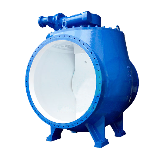
A ball valve operates by rotating a ball with a circular through-hole to control the flow. When the hole in the ball aligns with the pipeline direction, fluid can flow smoothly. When the ball rotates 90°, the hole becomes perpendicular to the pipeline, completely cutting off the flow. This "1/4 turn" design gives ball valves the advantages of quick opening and closing, as well as ease of operation, making them especially suitable for applications where rapid shut-off or connection of the medium is required.


2. Analysis of the Main Components of a Ball Valve

Understanding the core components of a ball valve is essential for making correct decisions during selection, maintenance, and troubleshooting. Below are the typical structural components of a standard ball valve.


(1) Valve Body

l  The main structural part of the ball valve, used to connect to the pipeline and withstand system pressure.

l  Common materials: carbon steel, stainless steel, brass, plastic, etc.

l  Types: one-piece, two-piece, and three-piece structures, which affect ease of maintenance and sealing performance.


(2) Ball

l  The core component that controls the flow of fluids.

l  The surface is typically precision-machined and chrome-plated to improve smoothness and corrosion resistance.

l  Can be divided into floating ball and trunnion (fixed ball) structures, designed to suit different pressure ratings and operating conditions.


(3) Seat

l  The annular component that forms the seal by contacting the ball.

l  Common materials: PTFE (Polytetrafluoroethylene), RPTFE (Reinforced PTFE), metal (used for high-temperature or abrasive media).

l  Plays a crucial role in sealing performance, and its quality directly affects the valve’s service life.


(4) Stem

l  The shaft that connects the actuator or handle to the ball, controlling the rotation of the ball.

l  Must have good tensile strength and corrosion resistance.

l  High-end ball valves are equipped with an anti-blowout design to ensure safety during operation.


(5) Packing & Gasket

l  Includes packing seals (such as V-type PTFE packing) and gaskets that connect the valve body, preventing external leakage.

l  For applications with frequent operation or high-temperature conditions, the seal material must be carefully selected to ensure compatibility.


(6) Operating Device (Handle / Actuator)

l  Manual ball valves are equipped with a handle, allowing a 90° rotation to open or close the valve.

l  Automatic control systems are fitted with electric or pneumatic actuators to enable remote or smart control.


3. Fluid Control Mechanism of Ball Valves

(1) Quick-Opening Flow Characteristics

Ball valves exhibit rapid flow changes during the opening and closing process, making them a "quick-opening" valve type. The relationship between the valve opening and flow is non-linear. Typically, ball valves are used for full-open or full-closed control in systems, and they are not suitable for precise flow regulation (except in specific structures like V-ball valves).


(2) Low Flow Resistance Channel Design

l  Full Port Ball Valve: The diameter of the passage is equal to the pipe diameter, resulting in almost no pressure drop. It is suitable for systems that require high flow rates.

l  Reduced Port Ball Valve: Saves material costs but introduces some flow resistance. It is suitable for most standard applications.


(3) Bidirectional and Unidirectional Sealing

l  Standard ball valves generally feature bidirectional sealing.

l  Certain special designs, such as ball valves with a check function, allow unidirectional flow. When installing, it is important to pay attention to the flow direction arrow.


(4) Special Structures and Performance Enhancement Designs

To meet the stringent requirements of various industries, ball valves have evolved into multiple enhanced versions based on traditional designs:

l  Floating Ball and Trunnion Ball Designs: Floating ball structures are suitable for small-bore, low-pressure systems, while trunnion ball structures are ideal for large-bore, high-pressure applications, providing lower operating torque and more stable sealing.

l  Fire-safe Design: Ensures that the valve maintains its sealing function under high temperatures or in fire conditions, ensuring safety.

l  Anti-static Devices: Used for flammable and explosive media to prevent sparks caused by static electricity during operation.

l  Anti-blowout Stem Design: Ensures that the valve stem will not be accidentally blown out under pressure, improving operational safety.
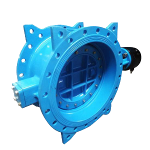
Wafer Check Valve vs. Swing Check Valve What's the Difference

Although wafer check valves and swing check valves serve the same functions—such as preventing backflow, enabling low-load pump startup, and reducing water hammer—they differ significantly in design standards, structural features, and areas of application. This article analyzes their differences across five key aspects to help users make more informed decisions when selecting a suitable valve type.


Difference 1: Design Standards

Wafer check valves are manufactured according to the following design standards:
• CJ/T 282-2008: Resilient Slow-Closing Butterfly Check Valve
• JB/T 5299-2022: Hydraulic-Controlled Butterfly Check Valve
• JB/T: Butterfly Pump Control Valve


In contrast, swing check valves follow these main standards:
• GB/T 12236-2008: Steel Swing Check Valves for Petroleum, Petrochemical, and Related Industries
• GB/T 13932-2016: Cast Iron Swing Check Valves
• API 6D-2021: International standard widely used in the oil and gas industry


It can be observed that wafer check valves are more commonly used in domestic municipal water systems, whereas swing check valves have broader global applicability, especially in demanding or high-standard working environments.


Difference 2: Distinct Structural Differences

The disc of a wafer (butterfly type) check valve is circular, with a pin shaft running through its center and positioned within the flow path. This results in a more compact design but can lead to increased flow resistance.

In contrast, the pin shaft of a swing check valve passes through the outer edge of the disc’s sealing surface and is located outside the flow path. This structural configuration allows the valve to operate more stably under medium to high pressure conditions.


Difference 3: Variation in the Use of Slow-Closing Structures

Due to their frequent use in large-diameter, low-pressure systems, butterfly check valves often feature slow-closing designs. The disc in such valves has greater movement inertia and is more susceptible to fluid impact, which can cause water hammer. To mitigate this, various slow-closing types are commonly used, such as:

Hydraulic automatic control valves

Dynamic flow check valves

Hydraulic-controlled butterfly check valves


On the other hand, swing check valves are typically applied in medium and small-diameter pipelines (DN15–DN600), where slow-closing structures are less common. Only a few models, such as the HH44X, incorporate this design feature.


Difference 4: Differences in Application Conditions

Butterfly check valves are primarily used in water systems and are well-suited for low- to medium-pressure applications, such as water treatment and municipal supply and drainage systems.

In contrast, swing check valves offer a broader range of applications and can be used in low-, medium-, and high-pressure conditions. They are suitable for a wide variety of media, including:

Water

Steam

Oil

Chemical fluids


When it comes to material selection, swing check valves are available in a wide range of options—from cast iron and cast steel to stainless steel and special alloys—making them ideal for handling more complex and demanding operating environments.


Difference 5: Differences in Pipeline Connection Methods

Butterfly check valves, due to their typically large diameter sizes, primarily use flange connections, while some smaller diameter models employ wafer (or lug) connections.

In contrast, swing check valves offer a wider variety of connection methods, including:

Threaded connections

Flanged connections

Wafer (or lug) connections

Welded connections

Clamp connections


This diversity in connection options makes swing check valves more flexible in installation, allowing them to better meet the demands of different piping system configurations.


Frequently Asked Questions (Q&A)

Q1: Are butterfly check valves suitable for high-pressure systems?

A: Generally, they are not recommended. Butterfly check valves are mainly used in low to medium pressure, large-diameter systems, and are less stable and reliable than swing check valves in high-pressure environments.


Q2: Why do butterfly check valves require a slow-closing (soft-close) design?

A: Because the valve disc is large and the opening/closing inertia is high, water hammer effects are easily generated. Therefore, most butterfly check valves are designed with a slow-closing mechanism to protect the system.


Q3: What working conditions are swing check valves suitable for?

A: Swing check valves are widely used for water, steam, oil, and corrosive media, especially in industrial applications requiring high sealing and pressure resistance.


Q4: Which type of check valve saves more installation space?

A: Butterfly check valves have a more compact structure and typically require less installation space, making them suitable for areas with limited space.


If you need help choosing the right check valve type for your specific application, please contact our technical team. We offer professional selection advice and customized solutions tailored to your needs.

What a Ball Valve Is Used For?

Ball Valve Overview


The ball valve evolved from the plug valve. Its closing element is a spherical ball that rotates 90° around the valve stem axis to open or close the valve. Unlike plug valves, the ball valve’s plug is spherical with a circular bore or passage running through its axis. When the ball rotates 90°, the inlet and outlet are completely blocked by the solid ball surface, effectively stopping fluid flow.


In pipeline systems, ball valves are mainly used for shut-off, distribution, and changing the flow direction of the medium. Ball valves designed with a V-shaped opening can also provide excellent flow regulation, making them suitable not only as shut-off valves but also as control valves in certain applications.


Structure and Performance Advantages


Ball valves feature a compact structure and excellent sealing performance. Within a certain nominal diameter range, they are characterized by small size, light weight, low material consumption, and reduced installation dimensions. They require a small operating torque, enabling easy and quick operation. These advantages have made ball valves one of the fastest-growing valve types over the past decade.


In industrialized countries such as the United States, Germany, France, Italy, Spain, and the United Kingdom, ball valves are widely used, with both variety and volume continuously increasing. Modern ball valves are evolving towards high temperature, high pressure, large diameter, high sealing capability, long service life, superior flow regulation, and multifunctionality. Their reliability and performance have reached advanced levels, and in some applications, they are gradually replacing gate valves, globe valves, and control valves.


Ball valves achieve tight shutoff with only a 90° rotation requiring minimal torque. The straight-through flow path inside the valve provides an almost unobstructed flow passage. Although traditionally used for on/off control, technological improvements have enabled some ball valves to perform throttling and flow control functions. Their compact design and easy maintenance make them suitable for conventional media such as water, solvents, acids, and natural gas, as well as stable operation under harsh media conditions like oxygen, hydrogen peroxide, methane, and ethylene. Ball valve bodies can be either integral or modular designs.


Application Prospects


With continuous technological advancements, ball valves will see expanded use in oil and gas pipelines, refining and cracking units, as well as the nuclear industry. Additionally, in other industrial sectors involving medium to large diameters and medium to low pressure conditions, ball valves are expected to become one of the mainstream valve types.


Advantages of Ball Valves


Low Fluid Resistance: Their resistance coefficient is nearly equivalent to that of a straight pipe of the same length.

Compact Structure and Lightweight: Small in size and easy to install.

Excellent Sealing Performance: Sealing surfaces often use high-performance materials like plastics, ensuring good performance even in vacuum systems.

Easy Operation: Quick on/off action with only a 90° rotation, suitable for remote control.

Convenient Maintenance: Simple structure with usually replaceable sealing rings, facilitating disassembly and servicing.

Sealing Surface Protection: In fully open or fully closed positions, the sealing surfaces of the ball and seat are isolated from the media, reducing erosion risk.

Wide Application Range: Applicable to nominal diameters from a few millimeters to several meters, and suitable for conditions from high vacuum to high pressure.


Common Questions Q&A


Q1: Is a ball valve suitable for frequent flow regulation?
A: Generally, ball valves are not recommended for frequent throttling unless specifically designed as V-port ball valves for regulation. Frequent adjustment may accelerate sealing surface wear.


Q2: Can ball valves be used for high-temperature or high-pressure media?
A: Yes, provided that appropriate body and sealing materials are selected. For example, metal-seated ball valves are suitable for high-temperature and high-pressure conditions.


Q3: What are common causes of leakage when a ball valve is closed?
A: Common causes include damaged sealing rings, worn ball surfaces, or foreign objects causing blockage. Cleaning, replacement, or repair should be performed based on the situation.


Q4: Are ball valves suitable for media containing particles?
A: For media with suspended particles, wear-resistant metal-seated ball valves should be used, along with regular flushing and maintenance to extend service life.


Q5: What is the biggest advantage of ball valves compared to gate valves?
A: Ball valves offer faster operation, smaller size, better sealing performance, and are easier to automate and control remotely.

What Is a Butterfly Valve and How to Identify It Quickly?

A butterfly valve is a type of rotary valve known for its compact structure, lightweight design, and fast opening and closing performance. It is widely used in industries such as water treatment, chemical processing, oil and gas, and power generation to shut off or regulate fluid flow.


What Is a Butterfly Valve?

A butterfly valve is a type of valve that uses a circular disc (also known as a "butterfly") which rotates 90 degrees around its own axis to open or close the flow path. Due to its simple structure, compact size, and flexible operation, it is particularly suitable for large-diameter, low-pressure piping systems.

A typical butterfly valve consists of a valve body, stem, disc, sealing ring, and actuator. Common actuation methods include manual, worm gear, pneumatic, and electric.


How to Identify a Butterfly Valve

Distinctive Appearance

A butterfly valve is easily recognizable by its central circular disc (butterfly) mounted on a central shaft, which rotates to open or close the valve. The overall shape is typically flat and round, making it visually distinct from ball valves or gate valves.


Short Rotation Angle

The disc generally rotates only 90 degrees to fully open or close the valve. This quick open-close mechanism is a key identifying feature.


Various Mounting Styles

Butterfly valves are commonly installed in wafer, flanged, or lug styles. These connection types are easy to distinguish and often conform to standard flange dimensions.


Wide Range of Applications

Butterfly valves are widely used in systems transporting water, air, gas, steam, or slurry. They are especially common in low to medium pressure and large-diameter pipelines.


Common Types of Butterfly Valves

Soft-Seated Butterfly Valve

Offers excellent sealing performance; suitable for low-pressure and room-temperature media.


Metal-Seated Butterfly Valve

Resistant to high temperature and pressure; ideal for industrial applications.


Triple Offset Butterfly Valve

Provides superior sealing capabilities; designed for high-pressure and high-temperature environments.


Conclusion

For engineers, procurement officers, or project managers, quickly identifying a butterfly valve and understanding its structure and function can lead to more efficient and safer decision-making during valve selection.


Thanks to their compact design, ease of maintenance, and cost-effectiveness, butterfly valves play a crucial role in many industrial applications.

What is the Difference Between Oil Filters and Strainers?

In hydraulic systems, lubrication systems, and even automotive engines, "clean oil" is the cornerstone of reliable operation. To filter out contaminants from oil, two common devices are used: oil filters and strainers. While often grouped under the umbrella term "filters" in Chinese, they serve distinct roles in engineering applications. This article dissects their differences across multiple dimensions to aid in selection, design, and maintenance decisions.


1. Filtration Precision and Working Principles


Strainers are designed for coarse filtration, typically using metal mesh or perforated plates with a filtration accuracy of 80–500 μm. They intercept large particles like metal shavings, sand, and debris.


Oil Filters focus on fine filtration, employing materials such as paper, cellulose, or synthetic fibers. Their precision ranges from 5–50 μm, with high-end models capable of removing particles smaller than 1 μm.


Key Distinction:

· Strainers act as the first line of defense, protecting systems at the inlet.

· Oil Filters serve as the secondary barrier, ensuring long-term oil cleanliness.


2. Installation Positions and System Roles


Device

Typical Installation Location

Functional Role

Strainer

Pump suction port, system inlet

Coarse filtration to block large particles from entering pumps

Oil Filter

Pressure lines, return lines, main oil circuits

Fine filtration to protect valves and actuators


In hydraulic or lubrication systems:

Strainers are often installed parallel to pumps to prevent wear; Oil Filters are placed in main circuits or return lines to "purify" oil, safeguarding precision components like proportional valves and servo valves.


3. Structure and Maintenance Methods


The strainer features a simple structure, low cost, and can be disassembled for cleaning and reused. It is suitable for occasions requiring large flow rates, low viscosity, and low precision requirements.


The oil filter has a complex structure, with most filter elements being single-use. The replacement cycle should be set according to working conditions, generally 500 to 1000 hours or as prompted by the differential pressure alarm.


In addition, the strainer is more suitable for systems with continuous operation and periodic maintenance, while the oil filter places greater emphasis on daily maintenance and long-term filtration efficiency.


4. Application Scenarios


Application

Recommended Device

Reason

Hydraulic pump suction line

Strainer

Prevents metal debris from entering pumps

Engine lubrication systems

Oil Filter

Removes combustion byproducts and fine wear particles

Industrial circulating oil systems

Strainer + Filter

Dual protection: coarse + fine filtration

High-pressure hydraulic systems

Oil Filter

Critical cleanliness requirements to prevent valve sticking


5. How to Scientifically Select Models in Practical Applications?


(1) Is Fine Filtration Required?

Yes: An oil filter must be installed.

No: A strainer alone may suffice.


(2) System Flow Rate and Contaminant Characteristics?

High viscosity or heavy particle load → Prioritize Strainers.

Precision components → Use high-accuracy Oil Filters.


(3) Maintenance Capabilities

Strainer: Reusable; suitable for systems with strong maintenance support.

Oil Filter: Easy replacement; ideal for automated systems.


6. Q&A


Q1: Can Strainers and Oil Filters be used independently?

A1: Depends on the application. Low-risk systems may use only a Strainer. For high-precision hydraulic/lubrication systems, combine both for multi-stage filtration.


Q2: What is the smallest particle a Strainer can filter?

A2: Typically 80–500 μm. Strainers cannot remove fine contaminants but protect pumps and lines from large debris.


Q3: How often should Oil Filters be replaced?

A3: Every 500–1,000 operating hours or when differential pressure alarms trigger. Adjust based on oil cleanliness and workload.


Q4: Do metal mesh Strainers never need replacement?

A4: While reusable, Strainers risk fatigue, corrosion, or clogging. Inspect regularly and replace if damaged.


Q5: Are Strainers or Oil Filters used in automotive engines?

A5: Both. A Strainer is installed at the pump inlet for coarse filtration, while a paper Oil Filter refines engine oil in circulation.

Why Are More Engineers Choosing 5A Duplex Stainless Steel Gate Valves for Harsh Operating Conditions?

Introduction

In industrial fluid control systems, gate valves, as a type of shut-off valve, have long played a key role in opening and closing operations. With increasingly complex operating conditions, higher demands are being placed on valves in terms of corrosion resistance, wear resistance, and service life.


Among the many available materials, duplex stainless steel (ASTM A995 5A) combined with hardfacing using Stellite (STL, cobalt-based alloy) has gradually become the preferred choice of engineers for harsh operating conditions. This configuration not only ensures the stability of the valve body in corrosive and high-pressure environments but also significantly enhances the durability and reliability of the sealing surface.


Material Analysis


1. ASTM A995 5A Duplex Stainless Steel

●  Advantages of duplex structure: Composed of ferrite and austenite, combining high strength with good toughness.

● Excellent corrosion resistance: Effectively resists chloride pitting, crevice corrosion, and stress corrosion cracking.

Stable mechanical properties: Maintains strong load-bearing capacity under high-pressure and high-strength conditions.


2. STL (Stellite Cobalt-Based Alloy Hardfacing)

● Outstanding wear resistance: Withstands severe erosion and mechanical abrasion.

● Extended sealing surface lifespan: Ensures stability of the seat and sealing surface, reducing leakage issues caused by wear.


Performance Advantages

Corrosion Resistance: Suitable for seawater, acidic media, and sour oil and gas environments.

Mechanical Strength: High-strength structure ensures pressure-bearing capacity with excellent fatigue resistance.

Reliable Sealing: STL hardfaced sealing surfaces provide superior wear resistance, reducing the need for frequent maintenance.

Extended Service Life: Material advantages significantly lower the total lifecycle cost of the valve.


Application Conditions

The 5A duplex stainless steel gate valve is widely applicable in the following conditions:

Offshore oil and gas production platforms

Chemical and petrochemical industries (acidic and high-chloride environments)

Seawater desalination and water treatment systems

Cryogenic conditions

Industrial pipelines with high chloride-induced corrosion risks


Conclusion

The ASTM A995 5A duplex steel + STL hard-facing welded gate valve, with its exceptional corrosion resistance, strength, and sealing reliability, is the ideal choice for demanding operating conditions. It not only maintains stability in high-corrosion and high-erosion environments but also effectively reduces maintenance frequency and the total lifecycle cost. In the future, with the ongoing expansion of energy development, marine engineering, and complex operating conditions, the application prospects of the 5A duplex steel gate valve will be even broader.


Q&A

Q1: What industries is the 5A duplex steel gate valve suitable for?

A1: It is widely used in pipeline systems for the oil and gas, chemical, seawater desalination, and high-chloride environments.


Q2: What are the advantages of the 5A duplex steel gate valve compared to regular stainless steel gate valves?

A2: The 5A duplex steel offers superior corrosion resistance and mechanical strength, while the STL hard-facing ensures wear resistance of the sealing surface. Together, they significantly extend the valve's service life.


Q3: Is the 5A duplex steel gate valve suitable for low-temperature conditions?

A3: Yes. It maintains toughness and stability at temperatures as low as -46°C, making it suitable for low-temperature storage and transportation systems.


Q4: How often does the 5A duplex steel gate valve require maintenance?


A4: Thanks to its material combination, the sealing surface is highly wear-resistant, and the overall corrosion resistance is strong. As a result, the maintenance frequency is lower compared to traditional valve materials.

Advantages of snow melting heating cable

Snow and ice accumulation on outdoor stairways in winter pose a significant safety hazard. Traditional snow removal, salting, or de-icing methods are not only inefficient and labor-intensive, but also damage the staircase materials and the environment. Heated cable snow removal systems offer a modern and sustainable solution.


Their key advantages are as follows:


1. Key Advantage: Superior Safety and Convenience

Completely Removes Snow and Ice, Eliminating Slip Risks

This is the most immediate and significant advantage. The system quickly melts snow, preventing its accumulation. This fundamentally eliminates the risk of falls caused by slippery stairs, maximizing the safety of the elderly, children, and all users.


Automated Operation Saves Time and Effort

This system typically features intelligent temperature and humidity sensors and an automatic controller. The system automatically activates when snow falls or temperatures drop, and automatically shuts down when the snow and ice melt. This eliminates the need to clear snow at night or early in the morning, saving significant labor.


Environmentally friendly and sturdy.

Alternative De-icing Agents: Chloride ions in traditional de-icing agents (salt) corrode metal stair components (such as handrails and fasteners) and attack the concrete surface, causing flaking and rusting, shortening the lifespan of the staircase. Heating cable systems completely eliminate this chemical corrosion.


Paving Material Protection: Freeze-thaw cycles (water expands when it freezes and contracts when it melts) can irreversibly damage paving materials such as tile and stone, causing cracking and chalking. De-icing systems eliminate the freezing process, effectively protecting the staircase structure.


2.Performance and Efficiency Advantages: Fast and Efficient Melting

Heating cables directly heat the ground, resulting in high heat conversion efficiency and a short heat transfer path. They melt snow faster than traditional hot air or hot water circulation systems.


Controlled Energy Consumption, Intelligent Energy Saving

Modern de-icing systems are highly intelligent. Instead of continuous heating, they precisely sense external conditions (such as precipitation and temperature) to activate on demand and operate only when needed, minimizing energy waste.


3. High Adaptability and Reliability

Flexible Installation and Adaptability

The heating cable is extremely slim and can be laid tightly around stair treads and landings of various shapes, perfectly adapting to straight, spiral, and custom staircases.


It can be installed in new construction or retrofitted to existing staircases.

Stable Operation and Low Maintenance

High-quality heating cables have a long service life (typically up to 50 years) and require virtually no maintenance after installation. The system is buried under cement mortar or adhesive, which is abrasion-resistant and UV-resistant, ensuring excellent stability and reliability.


4. Overall Benefits

Enhanced Property Image

For high-end commercial buildings, hotels, and residential complexes, a clean, safe, and accessible entrance, even in winter, demonstrates management's commitment to customer service and modern management, significantly enhancing the property's image and value.


Installation Considerations

To maximize the above benefits, please consider the following during installation:

Professional Design: Calculate local climate conditions and staircase heat dissipation to determine the required power supply and cable spacing.

Insulation: Installing a layer of insulation beneath the stair base is essential. It prevents downward heat loss and conducts heat upward to melt snow, improving energy efficiency by over 50% and significantly reducing operating costs.

Professional installation: Installation by an experienced team is essential to ensure even cable routing, avoid overlap, and achieve optimal electrical safety.

Conclusion: For slip-resistant snow melting on outdoor stairways, a heating cable system is the ideal solution: safe, efficient, environmentally friendly, and intelligent. While it requires a higher initial investment, its long-term value in terms of safety, maintenance costs, and building protection far surpasses all traditional methods, making it a highly cost-effective investment in modern buildings.

Difference Between Total Knee Replacement and Partial Knee Replacement A Complete Guide

Introduction

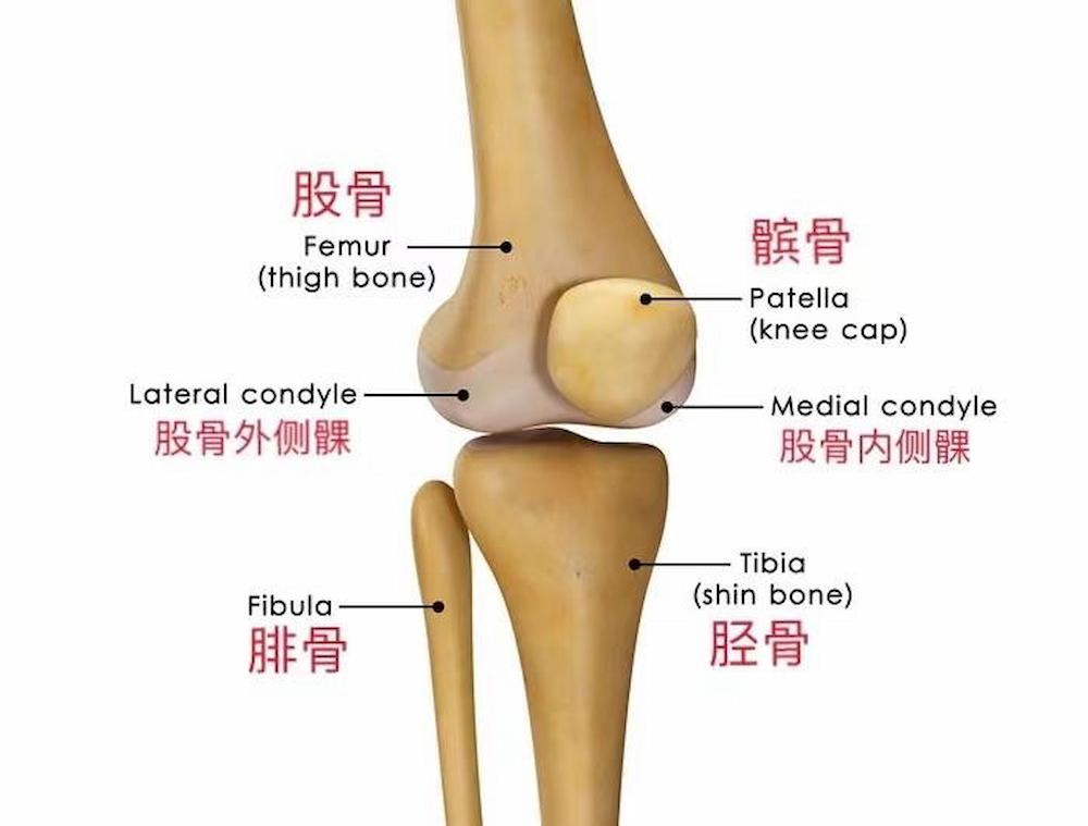
Knee replacement surgery has become one of the most common and successful orthopedic procedures worldwide. For patients suffering from severe knee pain due to osteoarthritis, rheumatoid arthritis, or traumatic injuries, two main options are available: Total Knee Replacement (TKA) and Partial Knee Replacement (UKA, also called Unicompartmental Knee Arthroplasty).

Although both involve the implantation of a knee prosthesis, their scope, surgical techniques, recovery times, and long-term outcomes differ significantly. Understanding these differences can help patients and surgeons make the most appropriate choice.


Knee Replacement

 
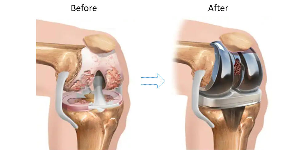
What Is Total Knee Replacement (TKA)?

In Total Knee Replacement, the damaged cartilage and bone from all three compartments of the knee joint (medial, lateral, and patellofemoral) are removed. An artificial prosthesis made of metal and polyethylene components replaces the entire joint surface.

  • Coverage: Whole knee joint
  • Implant: Femoral component, tibial component, and patellar button (optional)
  • Indications: Severe arthritis affecting multiple compartments, major deformities, or instability

Total Knee Replacement

 
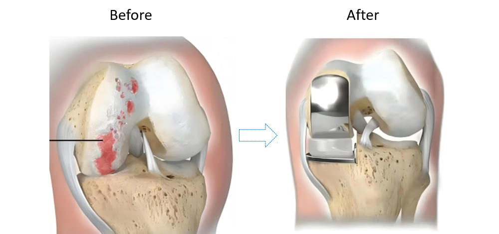
What Is Partial Knee Replacement (UKA)?

In Partial Knee Replacement, only the damaged part of the knee (usually the medial compartment) is replaced with a smaller prosthesis, while the healthy bone, cartilage, and ligaments remain intact.

  • Coverage: Only one compartment (medial, lateral, or patellofemoral)
  • Implant: Smaller femoral and tibial components
  • Indications: Early-stage osteoarthritis, pain localized to one side of the knee, preserved ligaments

 Partial Knee Replacement

 
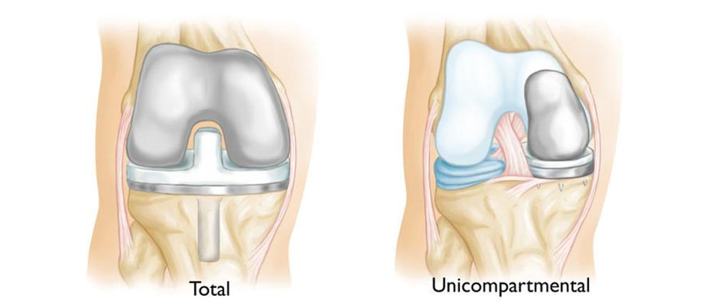
Key Differences Between TKA and UKA
Feature Total Knee Replacement (TKA) Partial Knee Replacement (UKA)
Surgical Scope Entire knee joint Single compartment only
Implant Size Larger prosthesis Smaller prosthesis
Bone Preservation More bone removed More natural bone preserved
Recovery Longer rehabilitation Faster recovery, less pain
Indications Severe arthritis, deformity Early-stage arthritis, localized damage
Longevity 15–20 years 10–15 years (may convert to TKA later)
 
Pros and Cons

Advantages of TKA

  • Effective for severe or advanced arthritis
  • Reliable long-term outcomes
  • Suitable for patients with deformity or ligament damage

Advantages of UKA

  • Less invasive, quicker recovery
  • More natural knee motion
  • Lower blood loss during surgery

Limitations

  • TKA: Longer rehabilitation, more bone resection
  • UKA: Not suitable if multiple compartments are damaged; higher risk of revision to TKA

TKA and UKA


Conclusion

Both Total Knee Replacement and Partial Knee Replacement are proven solutions for knee arthritis, but their suitability depends on the extent of joint damage and patient condition.

  • TKA offers a complete solution for advanced cases, ensuring long-term durability.
  • UKA provides a less invasive option for patients with localized arthritis, allowing faster recovery and more natural knee function.

When choosing between the two, patients should consult with their orthopedic surgeon, considering factors like age, activity level, and overall knee health.


Disposable Puncture Suturing Device | Dual-Function Puncture and Suturing, Effortless Puncture, Perfect Closure

Disposable Puncture Suturing Device

Laparoscopic surgery, as a minimally invasive technique, has been widely adopted in general surgery for various procedures. During laparoscopic surgery, surgical instruments access the abdominal cavity through trocars. After the procedure, puncture sites remain on the abdominal wall. Improper suturing of these sites can lead to complications such as bleeding, hematoma, infection, and trocar site herniation. Suturing the fascial layer of the puncture site effectively reduces the difficulty of incision closure in laparoscopic surgery, minimizes the risk of trocar site hernia, and enhances surgical safety.

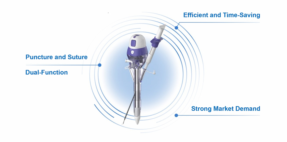
Trocars provide access for endoscopic instruments during laparoscopic surgery. A trocar with integrated suturing capability combines fascial closure functionality into the device, enabling both puncture and suturing in a single step. The disposable puncture suturing device consists of a cannula with a guide hole, a visual obturator, a suturing puncture needle with a side hole, and an abdominal wall puncture needle clamp for grasping the suture. The guide hole on the cannula is sealed with an ultra-thin silicone membrane to prevent air leakage during use.

Disposable Puncture Suturing Device

Schematic Diagram of Fascial Closure Mechanism


Product Advantages

Combines dual functions of puncture and suturing, eliminating the need for a separate fascial closure device—offering both medical and economic value.

Precise Visual Puncture: Significantly reduces the risk of organ injury.

Simplified Workflow: Easy to master with minimal training, ensuring efficient operation.

Time-Saving Technology: Rapid suturing enhances procedural efficiency.

Clear Visual Suturing: The suturing process is fully visible, ensuring accuracy and avoiding organ damage.

Broad Compatibility: The obturator is compatible with various commercially available cannulas—bladed or bladeless, disposable or reusable.


Strong Market Demand

Data indicates a substantial and steadily growing market demand for laparoscopic trocars. In 2019, sales of disposable trocars in China reached 18.4 million units, with a market value of RMB 1.77 billion. By 2024, this is projected to grow to RMB 5.091 billion, reflecting a compound annual growth rate (CAGR) of 23.4%.Disposable Puncture Suturing Device

Amid the trend of declining prices due to centralized medical procurement, conventional laparoscopic trocars are losing their competitive edge. In contrast, laparoscopic trocars with fascial closure functionality demonstrate significant clinical advantages. Their innovative design integrates both puncture access and fascial closure, aligning with the market's demand for advanced medical devices.

Efficient Orthodontic Assistant——Anchorage Mini-Implant

What is an anchorage mini-implant?

The anchorage mini-implant, also known as a micro-screw implant or bone anchor, can be simply understood as a means or device that serves as a fixed point for orthodontic forces.

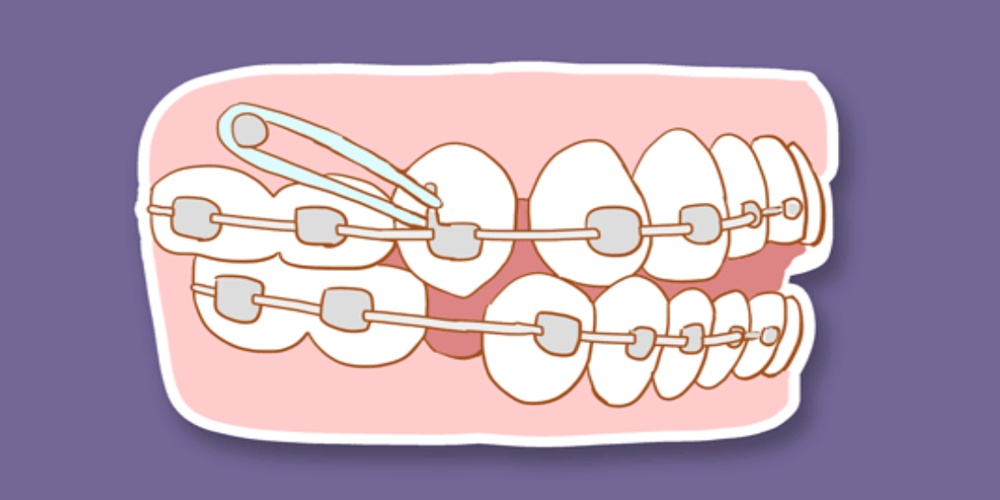
In conventional orthodontic treatments, such as wearing braces, the fulcrum for orthodontic forces is provided by other more robust teeth, which generate traction to move the teeth that need to be shifted to their designated positions.

This process is akin to a tug-of-war; without a significant difference in strength, it's generally a situation of you advance and I retreat, I advance and you retreat, a contest of tenacity and endurance.

Even the most robust teeth can be at risk of being dragged forward, which is, of course, a major taboo in orthodontic processes. Perfection-seeking dentists absolutely cannot tolerate such situations that affect the effect of teeth retraction.

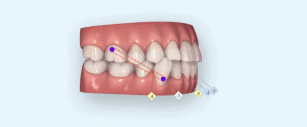
The emergence of anchorage mini-implants has effectively addressed the aforementioned issues. They can be fixed within the bone tissue, providing absolute anchorage. When applying traction to misaligned teeth, they can better control the movement of the teeth, in which direction they should move, and how much they should move.


Do all orthodontic treatments require anchorage mini-implants?

Of course not. Anchorage mini-implants are particularly effective for patients with severe skeletal deformities. If your correction involves the following situations, then the power of bone anchors will be needed.

1. Patients with protruding teeth: Those who need to improve the facial protrusion issue. By placing anchorage mini-implants, the protruding front teeth can be retracted, thereby maximizing the improvement of protrusion and improving the side profile.

2. Lowering upper and lower front teeth: With the help of anchorage mini-implants between the roots of the upper and lower front teeth, conditions such as uncoordinated lip-tooth relationships, gummy smiles, deep overbites, and underbites, caused by excessive eruption of upper and lower front teeth, can be improved by directly applying pressure to the anterior archwire through a chain loop, which is a simple and effective method.

3. When there are frequent issues with posterior teeth: When a posterior tooth is missing on one side, making it difficult to control the midline, anchorage mini-implants can be used; when posterior teeth are obstructing growth, anchorage mini-implants can also be used to straighten the tilted posterior teeth.

Many patients have insufficient understanding of anchorage mini-implants and have many doubts. Now let's address the common questions to alleviate your fears about getting anchorage mini-implants:


9 Questions About Anchorage Mini-Implants

1. What is the use of anchorage mini-implants?

Tooth movement is the result of the interaction between force and counterforce. The role of anchorage mini-implants is to resist the counterforce in place of teeth, providing a stable force for the teeth that need to be moved while avoiding unnecessary movement of other teeth.

2. What material are anchorage mini-implants made of?

Can they cause allergies? Anchorage mini-implants are generally made of pure titanium, titanium alloy, or stainless steel. They are required to have good biocompatibility and sufficient hardness to prevent the bone anchor from breaking during insertion. Before entering clinical use, they must first undergo biocompatibility testing and then clinical trials. Therefore, they do not cause allergic reactions.

3. Are there any risks with anchorage mini-implants?

The procedure for placing anchorage mini-implants generally involves disinfection, local anesthesia injection, and finally, the implantation of the mini-implant. The anesthesia is a local anesthetic, so there is no risk involved.

4. Does getting an anchorage mini-implant hurt?

Local anesthesia is required before placing an anchorage mini-implant, so there is no pain. After the effect of the anesthetic wears off, there may be local pain and discomfort. If the pain is severe, you can take painkillers as prescribed by a doctor, and it usually takes about three days to fully recover.

5. Where are anchorage mini-implants usually placed?

The placement of anchorage mini-implants needs to be coordinated with individual correction plans and varies from person to person. Whether it's the posterior or anterior tooth area, they are usually implanted between two teeth, avoiding the tooth roots. Special locations may also be chosen according to actual needs, such as the external oblique line of the mandible.

6. How should anchorage mini-implants be cared for?

When brushing your teeth, you can gently brush the anchorage mini-implant a few times to clean the food debris around it, or you can use a water flosser to rinse it. However, it is important not to use a vibrating electric toothbrush to clean the anchorage mini-implant to avoid loosening it.

7. Can anchorage mini-implants become loose?

What if they do? Anchorage mini-implants can become loose, for example, if food debris around the anchorage mini-implant is not cleaned, causing inflammation, the anchorage mini-implant will become loose. If it becomes loose, the anchorage mini-implant needs to be removed, disinfected, and replaced in a new position or re-implanted after the alveolar bone has recovered.

8. When should anchorage mini-implants be removed?

When anchorage mini-implants are no longer needed, they can be removed.

9. Will there be a wound after the anchorage mini-implant is removed?

Yes, there will be, but it will usually heal automatically within three to five days, so there is no need to worry.