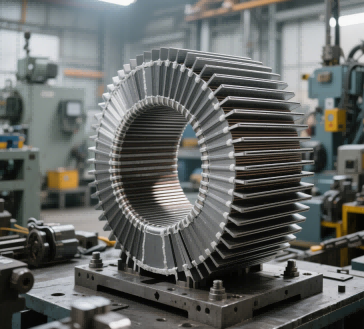
The transformer core (also known as the magnetic core) is the central magnetic circuit component of a transformer. Its material selection directly affects the transformer's efficiency, losses, and applicable scenarios. Based on operating frequency, power requirements, and cost factors, core materials can be categorized into the following types:
1. Traditional Silicon Steel Sheets (Fe-Si Alloy):
Composition:
Cold-rolled steel sheets with silicon content ranging from 0.8% to 4.8% , typically with a thickness of 0.35mm or thinner.
Characteristics:
High saturation magnetic induction (Bs≈1.6–1.7T), suitable for high-power scenarios at power frequencies (50/60 Hz).
Laminated stacking: Insulating coatings are applied between layers to reduce eddy current losses. However, losses increase significantly at high frequencies.
Applications:
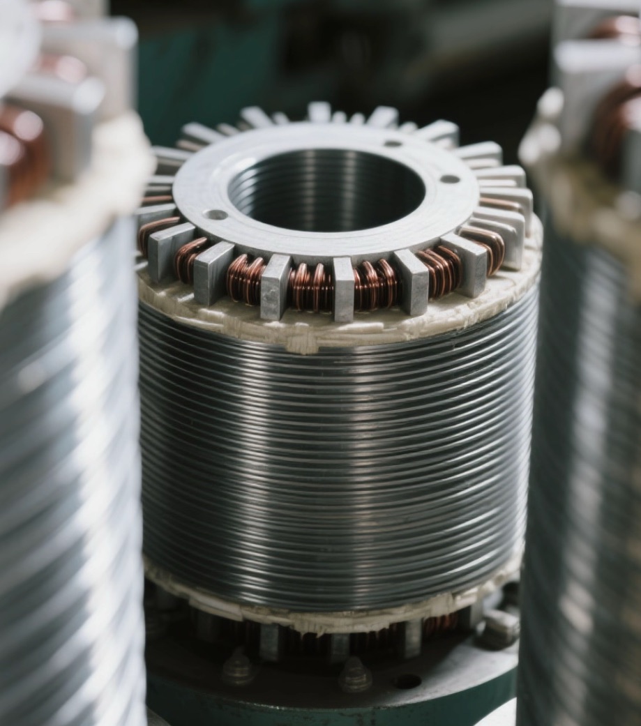
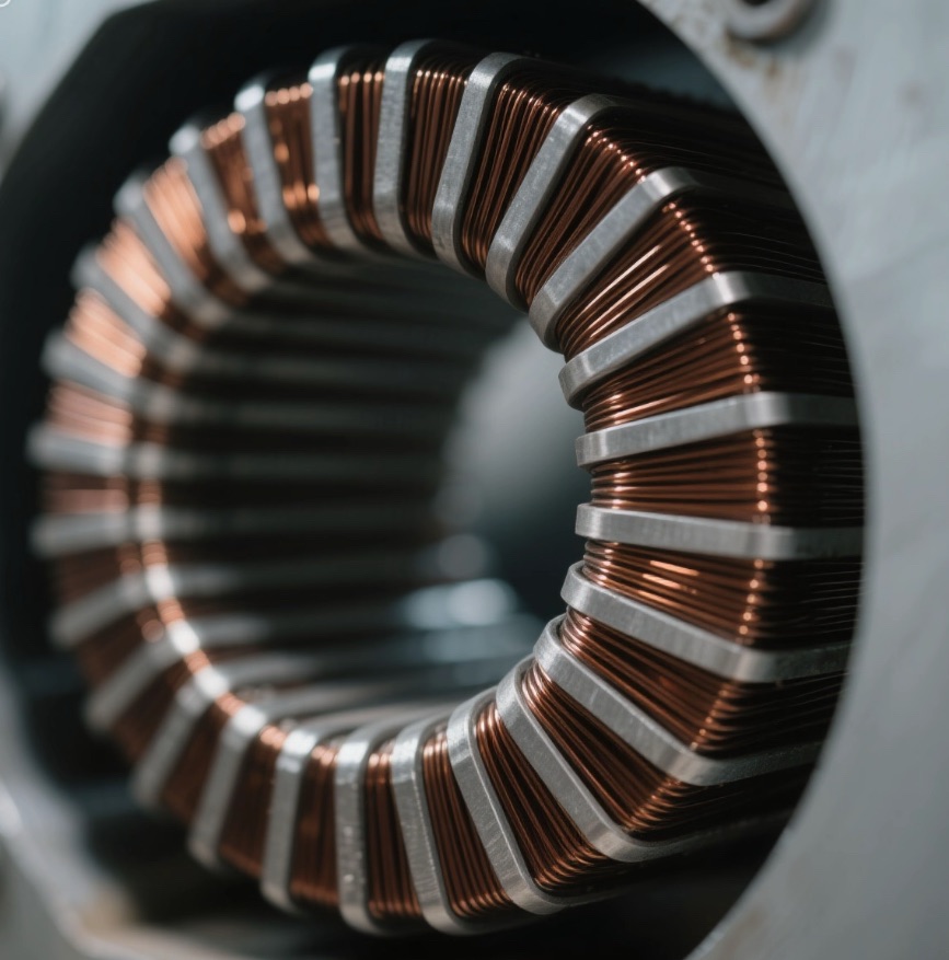
Primarily used in power transformers and motor cores for low-frequency, high-power electrical equipment.
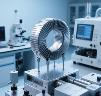
2. Ferrite Core
Composition:
Manganese-zinc (MnZn) or nickel-zinc (NiZn) ferrite, classified as sintered magnetic metal oxides.
Characteristics:
High resistivity: Significantly reduces eddy current losses at high frequencies, suitable for a frequency range of 1 kHz——1 MHz .
Low saturation flux density (Bs ≈<0.5T), weak DC bias capability, and prone to magnetic saturation.
Applications:
Widely used in electronic devices such as switch-mode power supplies (SMPS), high-frequency transformers, and inductors.
3. Metal Magnetic Powder Cores
Types:
Iron powder cores
Iron-silicon-aluminum powder cores (FeSiAl)
High-flux powder cores (HighFlux)
Molybdenum permalloy powder cores (MPP) .
Characteristics:
Strong anti-saturation capability: Reduces eddy currents through insulation-coated dispersed magnetic particles, making it suitable for DC superposition scenarios .
Medium permeability (μe≈10—125) with a frequency range of 10 kHz - 100 kHz .
Applications:
Widely used in medium-to-high-frequency power devices such as:
PFC inductors (Power Factor Correction)
Filter inductors.
4. Novel Alloy Materials
Amorphous Alloys
Composition:
Iron-based (e.g., Fe₈₀B₁₀Si₁₀) or cobalt-based amorphous ribbons, characterized by disordered atomic arrangement .
Advantages:
Ultra-low core losses (only 1/5 of silicon steel), enabling significant energy savings .
Limitation:
Significant magnetostriction (resulting in higher operating noise) .
Applications:
Energy-efficient distribution transformers.
Nanocrystalline Alloys
Structure:
Nano-scale crystalline grains (<50 nm) embedded in an amorphous matrix .
Advantages:
High permeability & low losses (superior to ferrites at 50 kHz) .
Strong harmonic resistance and excellent thermal stability (operating range: -40–120°C) .
Applications:
High-frequency transformers and PV inverters .
EV electric drive systems (e.g., integrated OBC/DC-DC modules)
Key Factors in Material Selection
Operating Frequency
Low Frequency (≤1 kHz) :
Silicon Steel or Amorphous Alloys (e.g., Fe₈₀B₁₀Si₁₀).
High Frequency (>10 kHz) :
Ferrite Cores (MnZn/NiZn) or Nanocrystalline Alloys.
Loss Requirements
Lowest Core Loss:
Amorphous/Nanocrystalline Alloys.
High-Frequency Loss Optimization:
Ferrites.
Cost and Process
Cost-Effectiveness & Maturity:
Silicon Steel.
High Initial Cost with Long-Term ROI:
Amorphous/Nanocrystalline Alloys.